


Development status of equipment for internal PCV investigation [TOSHIBA] (Aug.19, 2014)
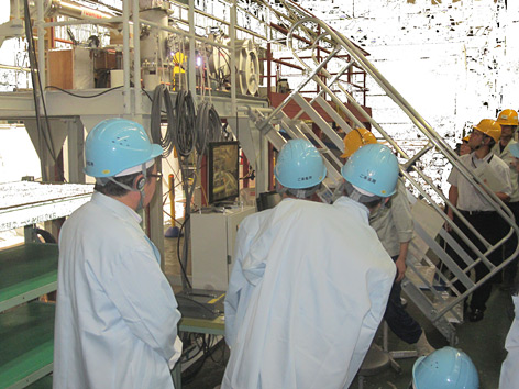
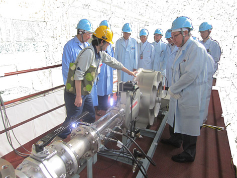
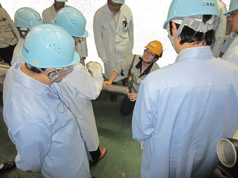
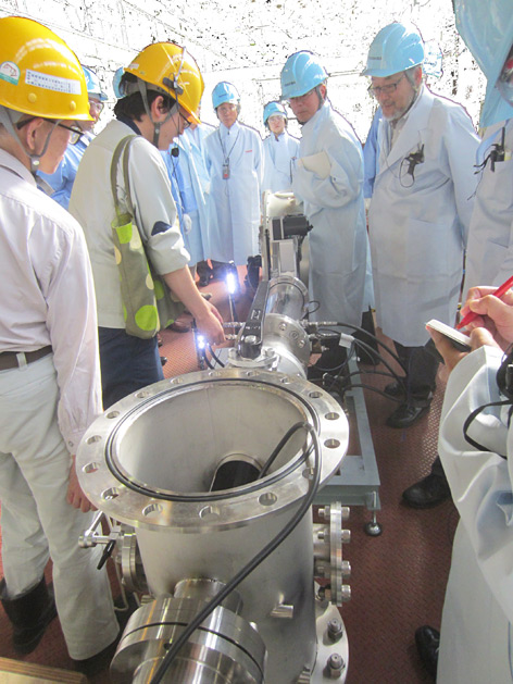
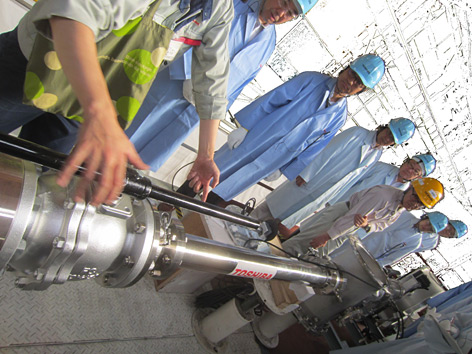
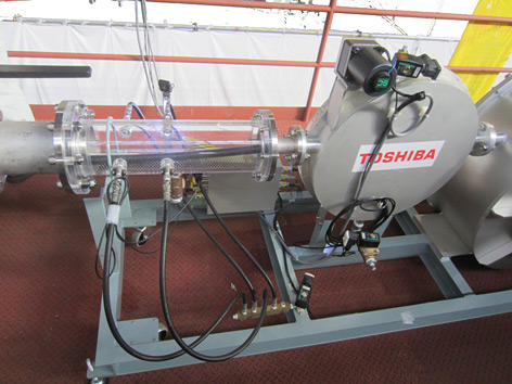
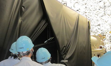
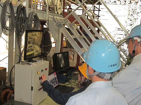
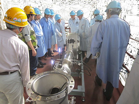
On Aug.19, 2014, members of IRID’s Technology Advisory Committee’s Subcommittee of Fuel Debris Retrieval Technologies (subcommittee overseeing the development of remote operation equipment/technology to retrieve fuel debris) visited IRID member Toshiba’s Keihin Product Operations, located in Tsurumi, Yokohama City. They observed equipment used for internal PCV investigation (robots etc.) and a mock-up test using full-scale equipment.
It is assumed overheated fuel melted along with control rods and other structural components inside the RPVs of Fukushima Daiichi NPS Units 1-3 solidified again after reaching the bottom of the RPVs, and partially at the bottom of the PCVs. This solidified material is called “fuel debris.”
Retrieval of the fuel debris from inside the PCV is an essential part of the decommissioning process, but workers cannot get near the structures with radiation levels inside the PCVs being tremendously high even now. The remote controlled robots therefore succeed in working to help engineers understand the conditions inside the PCV.
The most important task in the robot development process is to predict the site condition. Since current conditions are significantly different from those found under normal circumstances, various kinds of risks should be assumed.
We identified more than a hundred risk areas during the development process and are now focusing on developing countermeasures based on site conditions at the Fukushima Daiichi NPS and on the latest findings.
【Internal PCV investigation procedure】
- (1) The plan to investigate inside the PCV involves using the installed cylindrical structure (X6 penetration) leading to the inside of the PCV. Firstly, shield blocks in front of the X6 penetration will be removed by remote manipulation. Following this, isolation valves will be installed on theX6 penetration.
- (2) An extension pipe is then affixed, and an investigation device is inserted to panoramically check the access route for the investigation equipment in advance. This equipment can, if necessary, break cables inside the X-6 penetration which may obstruct the progress of the robot.
*This pipe is inserted up to the CRD replacement rail (a rail used as a replacement for the control rod drive unit). - (3) After securing the progress route by pushing down and crushing the aforementioned cables (if they are blocking the route), the rest of the unit, such as the guide pipe, is installed. A small crawler robot is then ready to be deployed.
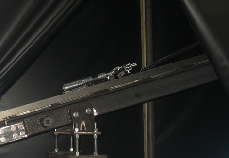
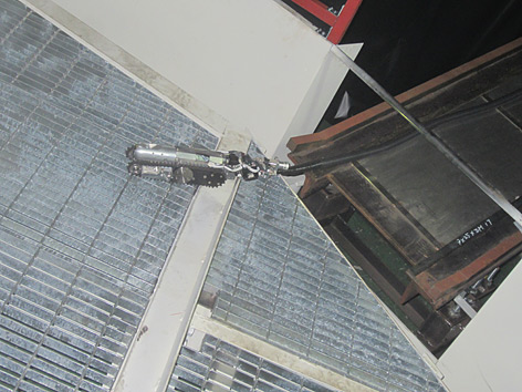
- (4) The hatch of the guide pipe opens downward, and it becomes a ramp to the CRD rail. A small-scale robot goes down the ramp slowly and is set at the specified place on the CRD rail. It then goes over the gap between the grouting on the CRD platform until it reaches its destination (on the grouting of the CRD platform).
The robot operator remotely operates these procedures by checking the images inside the cable wind device and the feeder taken by the cameras mounted on the front and back of the robot and the bird’s eye view camera installed at the end of the guide pipe. - (5) It is planned that a small-scale robot will check the inside of the PCV using the cameras installed on the back and front of the unit while running on the grouting and gathering information.
Testing of the equipment and training using the mock-up facility will continue. The equipment will be deployed at the Fukushima Daiichi NPS Unit 2 in the first half of FY2015.
Below is footage showing a series of movements that the small-scale robot starts at the guide pipe, runs over the grouting on the CRD platform, and the robot’s return. (Note: It has also been sped up x3 during editing).
Visit by the Technology Advisory Committee
- [Photos] Click image to enlarge.
- [Videos] Click “Download video” to download MP4 file.
[Photos]

[Videos]
- Research and Development
- Released research report
- FY 2017 R&D Report
- Introduction Research
- Survey Device (Shape-changing Robot) Deployed to Inspect Interior of Primary Containment Vessel (PCV)
- Work Training of Device (Shape-changing Robot) to Inspect Interior of Primary Containment Vessel (PCV) [Hitachi-GE Nuclear Energy]
- Development status of equipment for internal PCV investigation [TOSHIBA]
- Robots working inside the buildings at Fukushima Daiichi NPS (Part III) Swimming robot & Crawling robot
- Robots working inside the buildings at Fukushima Daiichi NPS (Part II) MHI-MEISTeR
- Robots working inside the buildings at Fukushima Daiichi NPS Rosemary & Sakura
- Development Status of PCV Leakage Investigation Devices (Toshiba)
- Preliminary Test for “Water Stoppage Method” by Grouting into the Vent Pipe